By Jake Hughes
•
September 9, 2026
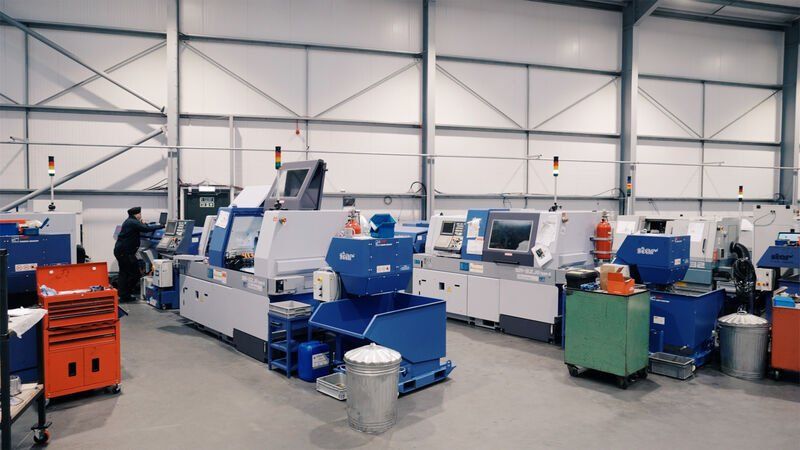
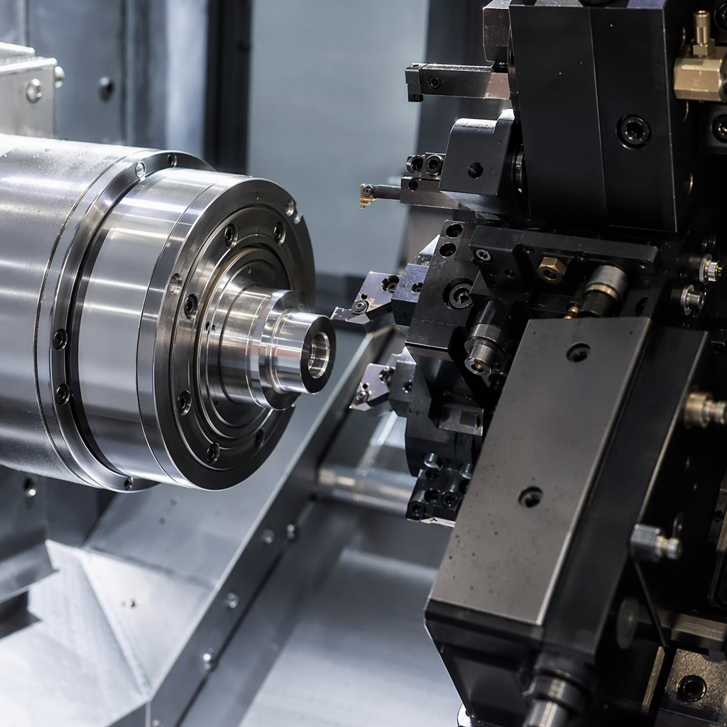
Key Highlights Sliding head turning supports bar stock at the cut using a guide bushing and sliding headstock. A CNC Swiss lathe is ideal for small, slender, complex parts needing high precision. It can combine turning, drilling, milling, and threading in one setup. This process helps control vibration and maintain tight tolerances on difficult geometries. Rotec runs 24 automated sliding head machines for prototype work and production volumes. Industries include aerospace, motorsport, military, rail, automotive, and industrial manufacturing. Introduction If you are comparing CNC suppliers for small, detailed parts, sliding head turning deserves close attention. This form of Swiss machining is built for precision components that are hard to machine on standard equipment. It uses a different method from regular CNC turning, giving better support to slender material during cutting. That matters when accuracy, repeatability, and fewer secondary operations affect cost, lead time, and part quality. The next sections explain how it works and when it makes sense. Sliding Head Turning Explained: What Is It and Why Does It Matter? A sliding head or Swiss-type CNC lathe feeds bar stock through a guide point near the tool instead of holding the work far back in a chuck. That simple change gives the process far better control on small, long, or detailed parts. In practice, a Swiss machine is used for complex components that need exceptional accuracy, stable repeatability, and efficient production. A CNC Swiss lathe is especially useful when you need high volumes, fine features, and fewer handoffs between machines. To understand why, it helps to start with the basic definition. Definition of Sliding Head (Swiss-Type) Turning Sliding head turning is a form of CNC turning designed for small, precise work made from bar stock. The machine uses a sliding headstock that moves the material along the Z axis while the tools cut very close to the support point. This differs from a conventional lathe, where the headstock stays fixed. The key part is the guide bushing. It supports the rotating material near the cutting zone, so the section being machined acts more like a short, stiff piece than a long, flexible bar. That reduces vibration, chatter, and bending during machining. Because of this layout, a Swiss machine is well suited to slim, detailed parts with tight dimensional control. Modern versions can also add milling, drilling, and threading in the same cycle, which helps reduce extra handling and improves consistency from part to part. Key Facts at a Glance: Capabilities and Applications At a glance, sliding head turning is built for small parts that need close control and repeat output. It is commonly used when standard turning struggles with part length, feature density, or tolerance demands. That makes it a strong choice for complex components in repeat manufacture. Rotec applies this process across sectors that need dependable quality and traceability. Its sliding head capability supports both sample work and high volumes, depending on the part and batch requirement. Best for small, slender, and complex parts with tight tolerance needs. A CNC Swiss lathe can combine several operations in one cycle. It is widely used where exceptional precision and repeatability matter. Suitable for prototype batches as well as high volumes. Common sectors include aerospace, space & satellite, motorsport, military, rail, and automotive. How Does a Sliding Head (Swiss-Type) CNC Lathe Work? A sliding head machine works by feeding material through a guide bush while the cutting tools stay close to the support point. The CNC Swiss lathe controls spindle movement, tool position, and feed with programmed accuracy, which is why Swiss turning is so effective on slender components. Unlike a fixed-head setup, the sliding headstock moves the bar itself. That reduces unsupported length during cutting and helps protect accuracy. To see how this happens, focus on the two core features first: the headstock and the guide bush. The Sliding Headstock and Guide Bush: Core Features The sliding headstock is what gives the process its name. Instead of spinning a part in one fixed position, the machine pushes or pulls bar material through the work zone. The cutting tool stays near the support point, so the tool is not trying to machine a long unsupported section. That support comes from the guide bush, sometimes called a guide bushing. It sits very close to the tool and holds the material steady as it rotates. This helps reduce deflection, vibration, and chatter, which are common problems on thin workpieces. For you, the result is practical. A properly set guide bush helps the machine hold high precision, better concentricity, and tighter tolerances on long or narrow forms. It also supports consistent surface quality across repeat runs, especially where a standard turning method may struggle. Bar Feed, Spindles, and Multi-Axis Machining A Swiss-type machine is not only about the guide system. It also relies on steady bar feed, spindle coordination, and strong CNC control. Bar feeders keep raw bar stock moving into the machine, which supports longer unattended runs and better output on repeat orders. The main spindle rotates and feeds the material. On more advanced equipment, a subspindle takes the part for back-working operations. This handoff lets the machine finish features on both ends without moving the part to another machine, which saves time and reduces alignment risk. Multi-axis machining adds another layer of capability. Rotec’s sliding head lathes can achieve up to 39 machining positions across 8 axes, often completing a component in a single setup. Its SR-32JIII Type B includes twin spindles, 3 turrets, 36 driven tools, 72 turning tools, and an automatic bar feed up to 42 mm diameter. What Makes Swiss-Type Turning Different from Fixed Head Turning? The main difference is where the workpiece is supported during cutting. In a fixed head lathe, the part is held at one end and the tool moves along it. In Swiss turning, the material passes through a support point near the tool, which changes how the part behaves under load. That design gives better control on small, slender shapes and complex geometries. Conventional lathes still make sense for larger diameters, heavier cuts, and faster job changes. The clearest way to compare both options is side by side. Comparison Table: Sliding Head vs. Fixed Head CNC Turning If you are deciding between processes, look at support method, part geometry, and setup economics. A sliding headstock machine is designed for small, long, detailed work. A fixed head lathe is often the better fit for larger, less slender parts. In short, Swiss-type CNC turning wins when geometry and accuracy are difficult. Standard CNC turning stays valuable where the speed of setup and larger-diameter capacity matter more. When to Choose Sliding Head or Fixed Head for Your Parts Choosing the right process depends on part size, shape, tolerance, and batch volume. Sliding head turning is usually the better option for parts under roughly 32 mm, especially when the length is more than three times the diameter and the drawing calls for close control. Fixed head turning is often better for larger diameters, simpler forms, or low-volume work that needs quick changeovers. The choice is not about which machine is better overall. It is about which machine suits your part with the least waste and risk. Consider sliding head turning when you need: Complex parts with several features completed in a single setup Better surface finishes and less part movement between operations Cost savings by reducing secondary operations Repeat batches where setup time is spread across more parts Advantages of Sliding Head Turning for Precision Engineering For precision machining, the biggest advantages are control, repeatability, and process consolidation. Sliding head turning supports the material where it is cut, which helps maintain high accuracy on features that may be unstable on a standard lathe. That is why it is widely used for tight tolerances on small components. There is also a production benefit. By combining several operations on one machine, you can reduce handling, shorten lead time, and lower waste. The next two sections break those gains into accuracy first, then faster cycle times and automation. Exceptional Accuracy and Tight Tolerances Accuracy starts with stability. In sliding head turning, the guide bush supports the material close to the cutting point, so the bar is less likely to bend away from the tool. That matters when you need narrow diameters, long lengths, or fine feature placement. This setup improves dimensional control and helps the machine deliver high accuracy with less chatter. Production tolerances down to about plus or minus 0.005 mm are routinely associated with this process on suitable work. It also supports better concentricity and cleaner repeat results over longer runs. For buyers and engineers, that means exceptional precision with fewer surprises during inspection. The process is especially valuable where consistent quality matters across many parts, not just the first few off the machine. It is one reason sliding head turning remains a strong choice for demanding precision work. Reduced Cycle Times and Automated Production Speed in this process comes from doing more without stopping. A well-configured machine can turn, drill, mill, groove, bore, screw-cut, and cross-drill in one cycle. That cuts down transfers, queue time, and waiting between separate operations. Automated bar feeding also supports longer, more stable runs. With modern cnc control, main spindle and subspindle work can be coordinated to reduce idle time, which helps deliver faster cycle times on complex repeat parts. This is where Swiss-type turning often becomes more economical than conventional methods. Rotec has built its service around that model. It operates 24 fully automated sliding head machines running around the clock, with staffed hours Monday to Friday, 7:30 am to 5 pm. That automated production approach supports both high volumes and practical cost savings without compromising repeatability. What Can You Make with Swiss-Type Sliding Head Lathes? Swiss-type sliding head lathes are used to make small, detailed, often cylindrical parts that need close control and repeat consistency. They are especially strong on slender parts and complex parts that combine turned and milled features in a compact envelope. Because the process supports a wide range of materials and several operations in one cycle, it suits many precision machining requirements. The best way to judge fit is to look at part size first, then the industries where these complex components are most common. Typical Part Types and Component Size Ranges Swiss turning is best known for small parts with long, narrow proportions and precise features. Typical examples include pins, fasteners, fittings, connectors, injector parts, and other cylindrical items with threads, flats, holes, or back-end details. Medical examples often include dental implants and bone screws. From the compiled process data, Swiss machining commonly handles bar diameters of roughly 2 mm to 38 mm, with some machines reaching larger capacities. Rotec states a practical component size range from as small as 1 mm diameter up to 50 mm diameter, depending on the application and machine used. That range is important if your part sits near the limits of standard turning. Small parts with complex features, long unsupported lengths, or strict tolerance needs often move toward sliding head technology because it offers better control where conventional turning becomes less stable. Industries Served: Aerospace, Automotive, Medical, and More The process is used across industries that need small, repeatable parts with close dimensional control. In the broader market, that includes aerospace , automotive , medical devices, and electronic components. Typical products include fasteners, fittings, connectors, and detailed valve or sensor parts. Rotec serves a wide industrial spread with sliding head machining. Its quality systems include ISO 9001:2015 and AS9100, which matter to buyers who need formal process control and traceability for precision supply. Examples of sectors served include: Aerospace, Space & Satellite, and Military Formula 1/Motorsport and Automotive Oil & Gas, Agricultural, and Rail Industrial manufacturing, where small repeat components and consistent output are essential Beginner’s Guide: Getting Started with Sliding Head Turning If you are new to Swiss CNC machining , start with the basics: the machine, the material, and the setup logic. A sliding head process depends heavily on correct bar stock, stable tooling, guide bush adjustment, and sound programming. It is more specialized than general turning, so preparation matters. That does not mean it is hard to understand. It means each stage must be controlled carefully. The next sections cover the essential equipment, then the step-by-step flow from material preparation through machining and quality checks. Essential Equipment, Resources, and Setup for Swiss-Type Machining A Swiss-type machine tool needs more than the lathe itself. You also need suitable bar feeders, correctly sized collets, a properly adjusted guide bush, and tooling that matches the part geometry and material. Since the bar runs through the support system, straightness and diameter consistency are critical from the start. The CNC lathe must also be configured for the planned sequence of operations. That includes spindle setup, tool positions, and any back-working steps. Tooling options may include turning tools, drilling tools, milling tools, and thread tools, depending on the part. For more advanced production, machine capability matters a lot. Rotec’s fleet includes Star sliding head machines, with four additional Star machines added in 2021. Continual investment like this helps maintain capability for both simple repeat parts and more complex, multi-operation work. Step-by-Step Process for Using a Sliding Head CNC Lathe The machining process follows a clear order, even though the machine itself is complex. First the material is prepared, then the guide system and tools are set, then the program is proved out, and finally the cycle is run with checks for part quality and tool condition. A CNC Swiss lathe works best when each stage is planned around part geometry, feature order, and chip control. Because many parts are completed in a single setup, small mistakes early in the process can affect the full cycle. The basic flow usually includes: Prepare bar stock and confirm material condition Set the machine, guide bush, and tooling positions Program operations and verify spindle timing Run the part, monitor tool wear, and inspect surface finishes Step 1: Preparing Your Bar Stock and Materials Everything starts with the right raw material. In sliding head work, bar stock must be consistent in size and straightness because it passes through the guide system during machining. Poor material quality can lead to chatter, extra wear, and dimensional drift. This process can handle a wide range of materials, but the exact grade affects speeds, chip formation, and coolant needs. Common examples from the compiled data include stainless steel, carbon steel, brass, aluminum, titanium, nickel alloys, copper, and engineering plastics. Each behaves differently at the tool tip. Material preparation is not only about selecting the grade. You also need to confirm bar diameter, straightness, and suitability for the guide bush. For guide-bushing work, centerless-ground stock with tight diameter control is commonly preferred because it supports stable running and predictable results. Step 2: Setting Up the Sliding Head Lathe and Guide Bush Setup on a sliding head lathe is more involved than on many standard turning machines. The machine tool must be prepared with the correct collet, tool arrangement, and guide bush setting before any production cycle begins. This stage has a strong effect on accuracy and stability. The guide bush needs the right clearance. Too tight, and the bar may galle or run poorly. Too loose, and the material loses the support that makes the process effective. Good setup keeps the cutting zone stable and protects both part quality and tool life. On any CNC lathe, correct alignment matters. On a Swiss-type machine, it matters even more because many operations are happening in a compact area. Careful setup helps prevent taper, chatter marks, drifting concentricity, and premature wear across the run. Step 3: Programming the CNC Machine for Multi-Axis Operations Programming a CNC Swiss lathe means planning movement, timing, and feature order very carefully. The CNC control must coordinate bar feed, spindle motion, tool changes, and any handoff to a sub-spindle. When live tooling is involved, the program also has to manage milling, drilling, or cross-hole features within the same cycle. This is why beginners should focus on sequence first. Multi-axis machining creates efficiency, but only when the operation order supports stable cutting and safe part transfer. Programs are often tested with simulation or prove-out runs to catch collisions and wasted motion before production begins. Complex geometries benefit most from this approach. A well-written program can complete front-end and back-end features without moving the component to another machine. That reduces handling risk and supports better repeatability across finished batches. Step 4: Running the Machining Cycle and Quality Checks Once the setup and program are proven, the machining process moves into production. Even with automation, the cycle still needs control. Operators watch spindle behavior, chip flow, part handoff, and machine condition to confirm everything stays stable through the run. Quality checks are essential because small changes can affect many parts quickly. In sliding head work, worn tools, poor material behavior, or drifting bush conditions may show up as taper, chatter, or size variation. Monitoring tool wear early helps avoid large scrap batches during unattended running. Good control supports exceptional surface finishes and repeat dimensions. It also builds consistent quality from first-off approval through the rest of the order. For buyers, that matters just as much as speed, because reliable output reduces inspection issues, rework, and delivery risk. Materials and Features: What Swiss-Type CNC Lathes Can Handle Swiss-type machines are versatile, but they are not material-blind. The process can machine a wide range of materials, yet bar quality, chip control, and tool selection strongly affect the result. That is especially true in CNC machining, where small features and long runs leave little room for variation. The process also handles more than plain turning. With the right cutting tool and machine configuration, it can produce complex parts with strong surface finishes while combining several operations in one cycle. The next sections cover materials first, then multi-process capability. Compatible Metals, Plastics, and Alloys Swiss-type turning can process many common engineering materials as long as they are suitable for bar-fed machining. From the compiled information, typical groups include free-cutting steels, stainless steel grades, brass, copper, aluminum, titanium, cobalt and nickel alloys, and engineering plastics such as PEEK, nylon, and acetal. The material choice affects chip formation, cutting speed, tool wear, and thermal behavior. Stainless steel and tougher alloys may need closer control, while brass and some free-cutting steels are often easier to machine. Plastics also work well, though heat must be watched to protect shape and finish. For best results, the bar stock itself must be consistent. Straightness and diameter control matter because the material passes through the guide system. When those basics are right, the process can deliver exceptional accuracy across a broad range of turned and milled part features. Machining Multiple Processes in One Setup One of the biggest strengths of this technology is process consolidation. A modern sliding head machine can combine turning, drilling, milling, grooving, boring, screw-cutting, and cross-drilling in a single setup. That means the part can often leave the machine close to complete. Live tooling and subspindle capability make this possible. Instead of moving the component between several machines, the process keeps work in one controlled cycle. That reduces alignment risk, handling time, and inspection issues linked to multiple transfers. There are limits, though. Setup takes longer, the machines are more specialized, and material quality matters more than on general turning equipment. Still, for complex parts that would otherwise need many secondary operations, the reduction in extra handling can create real cost savings and more stable repeat production. Conclusion In conclusion, sliding head (Swiss-type) turning is a game-changer in precision engineering, offering unmatched versatility and efficiency. With its ability to perform multiple operations in one setup, this machining method excels in producing intricate parts with tight tolerances across various industries, including aerospace and automotive. By understanding its capabilities and processes, you can make informed decisions that enhance production quality and reduce cycle times. If you're ready to explore how sliding head turning can benefit your projects, reach out to us for a free consultation and discover tailored solutions that meet your specific needs. Frequently Asked Questions What is the difference between sliding head and fixed head turning? The main difference is support during the machining process. A sliding headstock pushes material through a guide bushing near the cut, while a fixed head lathe holds the work at one end. That gives sliding head turning better control on slender parts than conventional CNC turning. What size parts can Swiss turning machines make? A CNC Swiss lathe is mainly used for small parts and slender parts made from bar stock. Compiled process guidance often places the range around 2 mm to 38 mm diameter, while Rotec states capability from 1 mm up to 50 mm diameter, depending on application and machine. Is sliding head turning the same as Swiss turning? Yes. Swiss turning and sliding head turning are different names for the same core CNC turning method. The process uses a sliding headstock and guide support to machine small precision components accurately. Today, a modern Swiss machine can also mill, drill, and thread within the same cycle. How does the guide bush improve machining accuracy? The guide bushing supports the material very close to the tool, which reduces bending and vibration during cutting. That helps the machine maintain high precision, tighter tolerances, and better surface finishes, especially on long or narrow parts where unsupported material would normally deflect.