~ CMM Inspection Explained: Ensuring Precision in CNC Machining ~
Key Highlights
- CMM inspection uses a coordinate measuring machine to verify part dimensions and geometric features with strong measurement accuracy.
- It supports dimensional inspection and quality control across various industries where part consistency matters.
- The process records data points on a component and compares them with CAD models or 2D drawings.
- CMM inspection helps confirm dimensional accuracy on complex machined parts.
- Rotec offers this service to improve manufacturing consistency and provide tailored inspection reports.
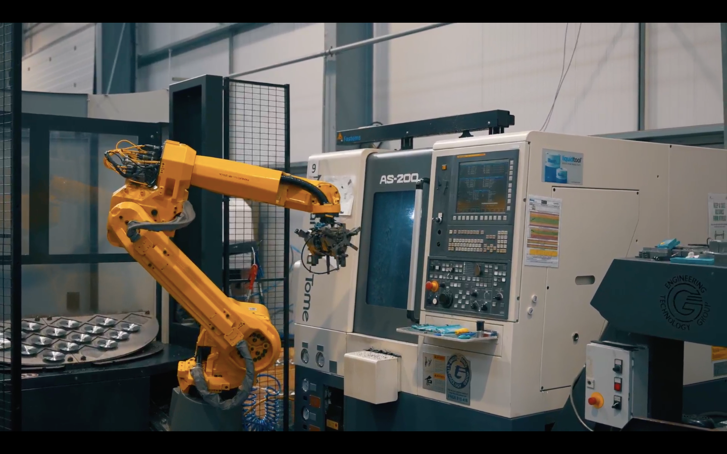
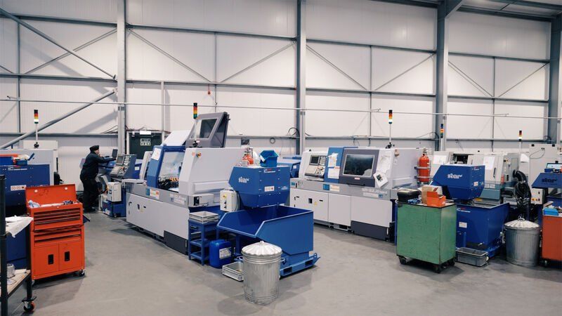
- It supports parts produced by sliding head turning, fixed head turning, and 3/4/5-axis CNC milling.
Introduction
If you buy or specify machined parts, you need proof that they match the drawing. That is where CMM inspection matters. A coordinate measuring machine gives precision measurement data that goes beyond basic shop-floor checks. It helps confirm whether a part meets the intended size, form, and position requirements. At Rotec, CMM inspection is offered to boost the accuracy and consistency of manufacturing processes, giving customers clear evidence that quality has been checked against the required reference.
Understanding CMM Inspection in CNC Manufacturing
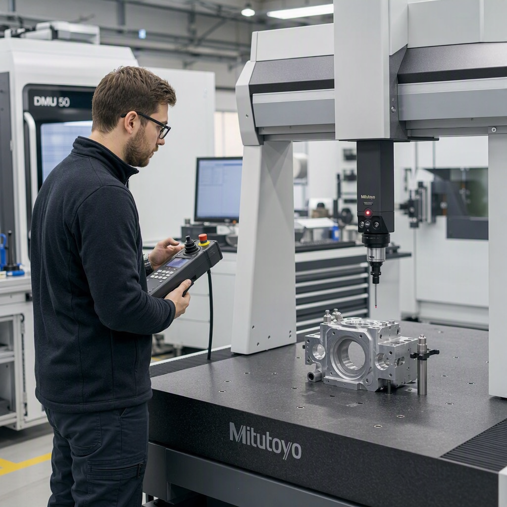
A coordinate measuring machine is a measurement system used to inspect the physical dimensions and geometric features of a part. In CNC machining, it helps verify whether finished components match design intent and meet required dimensional accuracy.
In simple terms, CMM inspection works by recording specific points from a part’s surface within a three-dimensional coordinate system. That data is then used for quality assurance and comparison against drawings or CAD references. To understand its value, it helps to start with the meaning of the term itself and why manufacturers rely on it.
What Does CMM Stand For, and Why Is It Used?
CMM stands for Coordinate Measuring Machine. It is a precision measurement system used to capture the exact positions of points on a part in a three-dimensional coordinate system. In quality control, “CMM checking” means inspecting a component to confirm that its measured features align with the required drawing or model.
You will usually see it used when manual tools cannot give enough coverage, repeatability, or confidence. A coordinate measuring machine can assess dimensions, locations, and geometric features on parts that would be difficult to verify consistently by hand. That makes it useful for modern manufacturing where quality standards are tightly controlled.
For buyers and engineers, the benefit is simple. CMM inspection provides objective evidence that a part has been measured against design requirements. At Rotec, this supports a broader quality-focused approach backed by ISO 9001:2015 and AS9100 accreditation.
How CMM Inspection Supports Dimensional Accuracy
CMM inspection supports dimensional accuracy by measuring physical objects in a fixed coordinate system and turning those readings into usable inspection data. This gives you a clearer picture of whether a part’s size, position, and geometry match the drawing. It also improves measurement accuracy by reducing variation in how checks are performed.
In quality assurance, that matters because small errors can affect fit, assembly, and performance. A structured digital measurement process helps teams spot issues earlier and verify finished components with more confidence.
Key ways it helps include:
- checking multiple measurement points across complex parts
- comparing actual results with design specifications for tolerance verification
- producing repeatable dimensional inspection data for quality control
For manufacturers and customers alike, that leads to more reliable decisions. It is one reason CMM inspection is widely used where consistency is critical.
Key Components of a Coordinate Measuring Machine (CMM)
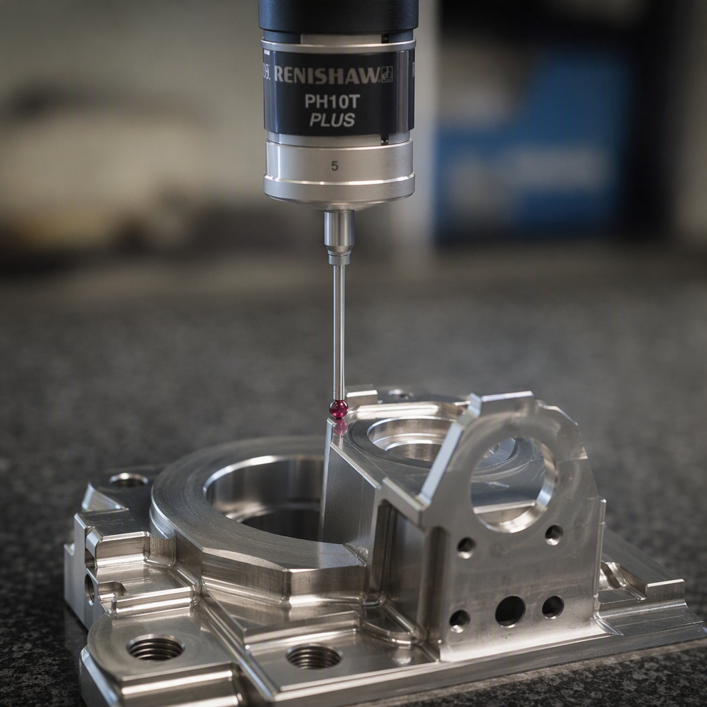
A coordinate measuring machine relies on several key components working together as one measurement system. These usually include the machine structure, movement along the axes, a probing system, fixtures for part stability, and software for data processing.
Each part of the CMM machine affects how measurements are captured and analyzed. Stable support, controlled movement, and reliable sensing all matter when you need repeatable results. The next sections break down the main elements so you can see how the system supports accurate inspection.
Structure, Axes, and Movement Mechanisms
The structure of a CMM provides the stable framework needed for accurate movement and measurement. Many systems use a rigid base, often a granite table, to reduce vibration and support the part during inspection. Above that, the machine moves along X, Y, and Z axes to reach specific points on the component.
These movement mechanisms matter because the probe must travel in a controlled way. A common arrangement is a bridge structure, where the measuring head moves over the work area. Different machine layouts exist, but they all aim to position the probe precisely.
| Component | Function in the measurement system |
|---|---|
| Granite table | Provides a stable, rigid surface for part set-up and inspection |
| X, Y and Z axes | Allow controlled movement through the Cartesian coordinate system. |
| Bridge structure | Supports motion across the inspection area on many bridge machines |
| Fixtures | Hold the part securely and reduce movement during checks. |
| Movement mechanisms | Guide smooth travel to target measurement points |
Probe Systems and Sensor Technology
The probing system is the part of the CMM that gathers measurement data from the component. In simple terms, the probe tip reaches the part and records points on its surface. Some systems use physical contact, while others use non-contact sensor technology such as laser, camera, or white light methods.
A common industry approach is the touch-trigger probe, which collects discrete data points when the stylus meets the surface. Non-contact options can capture many points quickly and may suit fragile or flexible parts better. The choice depends on the shape, material, and inspection need.
Accuracy comes from controlled movement, stable set-up, and proper data collection. If the right probing system is matched to the job, the machine can produce reliable results on complex geometries without relying heavily on operator judgement.
Software and Data Processing in CMMs
CMM software turns raw data collection into usable inspection results. Once the machine captures measurement data, the software processes those points and compares them with the required reference. That is the basic principle behind CMM operation: gather accurate coordinates, then analyze them against design intent.
Depending on the method used, the system may work with discrete points or a larger point cloud. The software then evaluates dimensions, positions, and geometric features. This makes it easier to assess whether the part meets the drawing or CAD models supplied for inspection.
At Rotec, CMM inspection uses CAD models and 2D drawing formats as reference sources. The result is a detailed inspection report tailored to each client and process. For a buyer or quality manager, that means the output is linked directly to the specification that matters.
How Does a CMM Inspection Process Work?
The CMM inspection process follows a clear sequence. A part is set up, measured through planned measurement routines, and checked against the required reference. This gives you precision measurement data that supports quality control and tolerance verification.
Although the details vary by component, the logic stays consistent. The aim is to create repeatable results, reduce avoidable variation, and provide evidence that the part matches the specification. The next two sections show the workflow and the role of CAD comparison and reporting.
Step-by-Step Workflow for Precision Measurement
A standard CMM inspection process starts with part set-up and reference alignment. The component is secured so it stays stable during measurement. The machine then follows programmed or guided measurement processes to collect discrete points or other surface data from the required features.
In simple terms, the workflow looks like this:
- CAD or 2D drawing reference is loaded and the part is set up
- The machine captures measurement points from selected features
- The data is compared with the specification and used to create a report
This process is valuable because it links precision measurement to a clear quality outcome. At Rotec, the reference comes from CAD models and 2D drawing formats, and the final report is tailored to the client and process. That helps engineers and buyers review results in a more practical way.
The Role of CAD Comparison and Inspection Reports
CAD comparison is one of the main reasons manufacturers use CMM inspection. Instead of checking only a few dimensions in isolation, the system can compare measurement data against CAD models or drawing references. This makes it easier to judge whether the part reflects the intended design specifications.
Inspection reports then turn that analysis into something you can act on. A good report shows what was measured and how the results relate to the specification. For quality teams, that supports traceable review and clearer communication with production or procurement.
At Rotec, inspection reports are tailored to each client and process rather than treated as a one-size-fits-all output. That matters when different sectors, parts, and quality standards demand different levels of verification. It also gives customers stronger confidence in supplied components.
Types of Coordinate Measuring Machines Used in Industry
More than one type of CMM is used across various industries. The right measurement system depends on part size, geometry, access requirements, and whether the job involves small components or heavy parts.
Common machine categories include bridge, cantilever, gantry, horizontal arm, portable, and optical systems. Each suits a different inspection task. If you understand the strengths of each type of CMM, it becomes easier to judge which inspection approach fits your component and production environment.
Bridge, Cantilever, and Gantry CMMs
Bridge machines are often seen as the most common type of CMM. They usually work over a granite table and use a bridge structure to move the probe across the part. This arrangement suits many small- to medium-sized components and offers a stable inspection setup.
Cantilever systems are supported from one side, which gives easier access to the part from several directions. That can be useful for smaller parts where operator access matters. The trade-off is that these machines are generally less rigid than two-sided structures.
Gantry CMMs are designed for large parts and heavy parts that are not easy to place on a table. In these cases, the machine spans the work area instead. Another industrial format is the horizontal arm style, often used for larger, lighter structures that need broad access rather than compact table-based inspection.
Portable, Optical, and Advanced Probing Variants
Not every inspection task suits a fixed machine. Portable CMMs allow measurements to be taken closer to the part, which can help on larger assemblies or where moving the component is not practical. Optical CMMs use non-contact methods to inspect the surface without physical contact.
These variants are useful in cases such as
- fragile or flexible parts where contact may not be ideal
- larger assemblies that are difficult to bring to a fixed measurement area
- reverse engineering or surface capture using optical data methods such as white light
Advanced probing expands what a system can inspect, but the principle stays the same. The machine gathers reliable data from the part and compares it with the required reference. The best choice depends on the material, shape, and inspection objective rather than one method always being better.
Applications of CMM Inspection Across Critical Industries
CMM inspection is used across various industries where dimensional confidence is essential. It supports quality assurance by checking complex parts during or after the manufacturing process and helps confirm that important features meet the required specification.
This matters most in sectors where accuracy affects performance, assembly, or safety. Rotec serves industries including aerospace, space & satellite, Formula 1/Motorsport, military, oil & gas, automotive, agriculture, rail, and industrial, where inspection quality is often a key buying factor. The following examples show where that value is most visible.
Aerospace, Automotive, and Medical Sectors
In aerospace, CMM inspection is important because aerospace components often have demanding design requirements and complex geometric features. Measurement accuracy helps confirm that machined parts align with the drawing before they move into critical assemblies. That is one reason inspection capability matters when choosing a supplier.
In automotive, the same logic applies to performance, fit, and consistency. Parts need to match specification across repeated production runs, not just in a single sample. Reliable dimensional inspection supports that goal and helps reduce variation.
Medical work also depends on careful verification because patient safety is tied to correct part form and size. While Rotec highlights a wide range of sectors, including aerospace and automotive, the wider industry use of CMM technology shows why buyers in regulated or performance-led sectors ask detailed inspection questions early.
Use Cases in CNC Machining and Sliding Head Turning
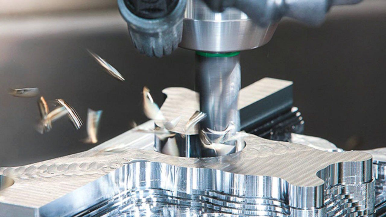
CMM inspection is especially useful in CNC machining because machined parts often include critical diameters, positions, and complex geometries that need reliable verification. It helps confirm whether the finished component reflects the drawing and supports high-precision production without relying only on manual checks.
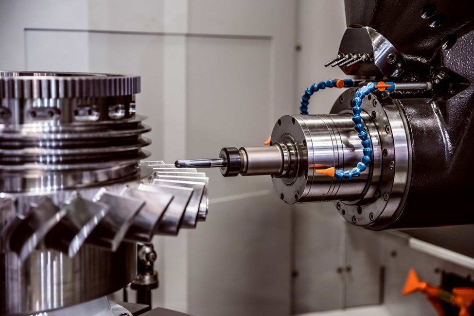
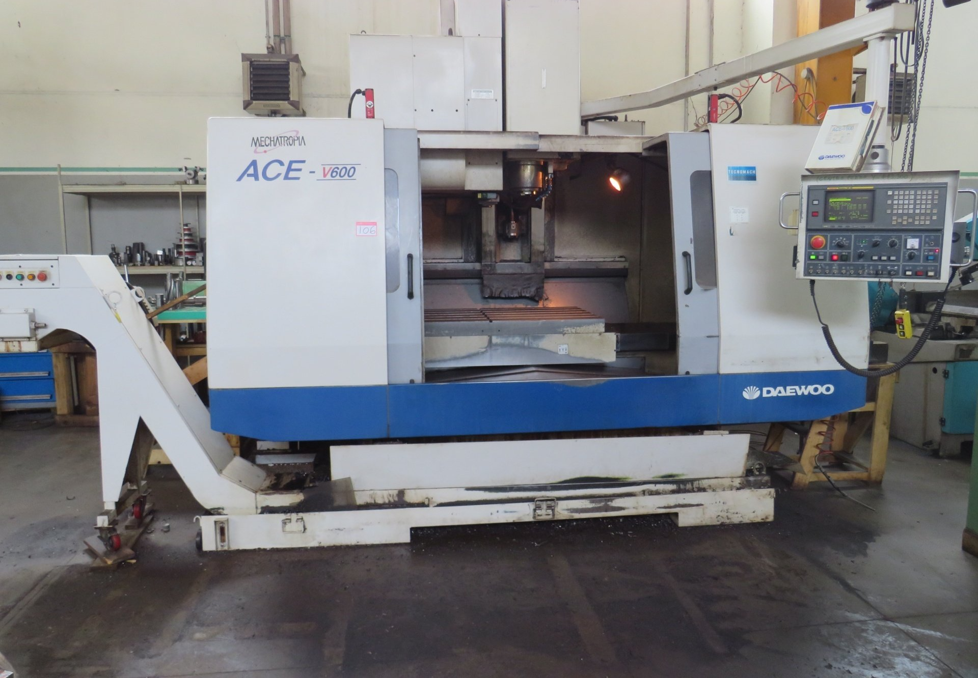
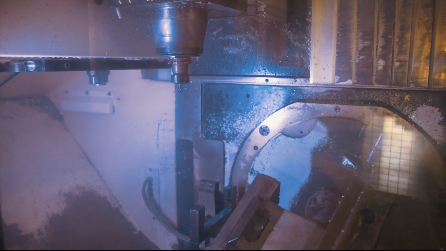
At Rotec, this inspection service sits alongside core capabilities in sliding head turning, fixed head turning, and 3/4/5-axis CNC milling. One referenced 5-axis machine also includes built-in probe inspection capability, combining simultaneous 5-axis machining, a swivel rotary table, a 12,000 rpm spindle, a 24-position tool changer, and probe inspection.
Typical use cases include:
- verifying components from sliding head turning for repeat production
- supporting CNC quality inspection on milled parts with complex features
- checking parts against customer drawings to support quality standards
For related services, you can visit Rotec’s CMM inspection service page, /sliding-head-machining-services-uk, and /cnc-turning-services-uk on rotec-ltd.com.
Conclusion
In conclusion, CMM inspection is an essential component in maintaining the precision and quality of CNC machining processes. By utilizing coordinate measuring machines, manufacturers can ensure that their components meet stringent dimensional accuracy requirements across various industries, from aerospace to automotive. This meticulous approach to quality control not only enhances product reliability but also reinforces your business's reputation for excellence. If you're interested in optimizing your manufacturing processes with top-notch CMM inspection services, don't hesitate to contact us at Rotec Aerospace Limited for a quote or consultation.
Frequently Asked Questions
What is the difference between CMM inspection and manual measurement?
CMM inspection uses a controlled digital system to capture measurement data across multiple points on a part. Manual measurement relies more on operator technique and is usually better for simpler checks. For tighter quality standards, CMM inspection can improve measurement accuracy and reduce the risk of human error.
How accurate is CMM inspection in verifying components?
CMM inspection is widely used for high-accuracy verification because it measures specific features in a structured coordinate system and compares them with design specifications. Exact capability depends on the machine, set-up, and method used, but it is trusted for precise measurements where consistency and repeatability are important.
When should CMM inspection be chosen over other methods?
Choose CMM inspection when parts have complex shapes, critical geometric features, or quality requirements that need stronger evidence than basic checks can provide. It is often one of the best practices for precision measurement when CAD comparison, repeatable reporting, and clear quality assurance records are important.